Watch video clip.
In the novel, The Hunt for Red October by Tom Clancy (Naval Institute Press, Annapolis, 1984), a fictional submarine is described where the propulsion system moved water without pushing on it with any solid moving parts. This kind of system has been called a "magneto-hydrodynamic drive" or simply an "ion engine."
A classroom demonstration of the ion engine was described by W. H. van den Berg and K. A. Miller in "Moving Water with No Moving Parts," The Physics Teacher, Vol. 35, Dec. 1997, p. 531. An actual model boat using an ion engine was described by G. I. Font and S. C. Dudley in "Magnetohydrodynamic Propulsion for the Classroom," The Physics Teacher, Vol. 42, Oct. 2004, p. 410. The following is a description of how we implemented a classroom demonstration of the ion engine.
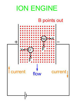
Two electrodes connected to a dc power supply are placed in salt water (saturated solution of NaCl). This produces a current of ions between the two plates. The positive-charged Na ions move towards the negative electrode and the negative-charged Cl ions move towards the positive electrode.
Fig. 1. Theory of operation. You may shift click on this image to download a pdf file from which a color transparency of this image can be made.
Two magnets attached to the apparatus produce a magnetic field pointing in a direction perpendicular to the motion of the ions. Both Na and Cl ions experience a force in the same direction, causing the ions to gain some motion in that direction. Collisions of the ions with the water molecules causes a net flow of the entire solution in that direction.
Plans for construction of the engine are shown below.
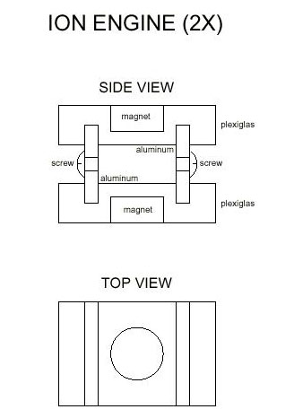
Fig. 2. Plans for construction. You may shift click on this image to download a pdf file. If you print this file, you will obtain plans which are scaled exactly 2:1 (2 inches on the plan equals 1 inch on the actual engine.)
The electrodes are made from two small aluminum plates. A brass screw in each electrode fastens the wire from the power supply. Two plexiglas forms hold the electrodes. They also hold two small magnets which, of course, are oriented so that they attract each other. We use half-inch diameter rare-earth magnets which provide a very strong field. Also, their strong attraction to each other holds the apparatus together.
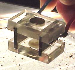
Fig. 3. Assembled ion engine.
To demonstrate the operation of the engine, we place it in a petri dish (glass dish with a flat bottom). A saturated solution of NaCl is poured into the dish until the electrodes are approximately half submerged. Pepper is sprinkled on top of the water so that the flow can be easily seen.
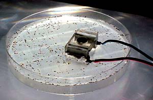
Fig. 4. Ion engine in operation.
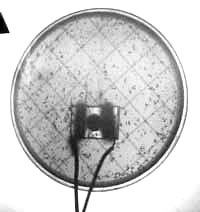
Fig. 5. Overhead projection of ion engine operation onto a screen.
The operation of the engine can shown in a large lecture hall by placing it on an overhead projector. The effect is quite dramatic. The water shoots through the engine with an amazingly fast speed.
We did encounter one bothersome problem. Chemical reactions at the electrodes causes a precipitate to form which eventually muddies the solution.
The amount of current required from the power supply depends on how fast you want the solution to shoot through the engine. More current produces a bigger effect but also causes the precipitate to form more quickly so that the demonstration has a shorter life. Generally we apply a few volts across the electrodes, drawing an amp or so of current from the power supply.